Basic Tutorial
This tutorial consists of a set of examples that will guide you on how to create a basic PCell, manipulate layout elements, and connect process data to your design.
Parameterized Cell
First, we have to understand the basic PCell template structure innate to any SPiRA design environment.
Demonstrates
- How to create a parameterized cell by inheriting form
spira.PCell. - How to add parameters to the cell.
- How to validate received parameters.
The first step in any SPiRA design environment is to import the framework:
import spira.all as spira
The spira namespace contains all the important functions and classes provided by the framework.
In order to create a layout cell all classes has to inherit from spira.PCell:
class Resistor(spira.PCell):
    """ My first parameterized resistor cell. """
The spira.PCell class connects the design to the SPiRA core. In the exampe above we created
a parameterized cell of type Resistor and a basic description given in qoutation marks.
Now that a layout class has been constructed we need to define a set of parameters that will
describe relations between layout elements.
class Resistor(spira.PCell):
    """ My first parameterized resistor cell. """

    width = spira.FloatParameter(default=0.3, doc='Width of the shunt resistance.')
    length = spira.FloatParameter(default=1.0, doc='Length of the shunt resistance.')
We defined two float restricted parameters, the width and the length of the resistor,
along with documentation (using the doc attribute) and a default value equal to \(0.3\) and \(1.0\), respectively.
class Resistor(spira.PCell):
    """ My first parameterized resistor cell. """

    width = spira.FloatParameter(default=0.3, doc='Width of the shunt resistance.')
    length = spira.FloatParameter(default=1.0, doc='Length of the shunt resistance.')

    def validate_parameters(self):
        if self.width > self.length:
            raise ValueError('`Width` cannot be larger than `length`.')
        return True
By definition we want to make sure the length of of the resistor is larger than the width.
To check the validity of the parameters in relation to eachother, we can use the validate_parameters() method:
This method consists of a series of if-statements that checks whether the defined parameters are valid or not after instantiation.
# 1. First create an instance of the resistor class.
>>> D = Resistor()

# 2. You van view the default values of the parameters.
>>> (D.width, D.length)
(0.3, 1.0)

# 3. The parameter is successfully updated if it is valid.
>>> D.width = 0.5
>>> (D.width, D.length)
(0.5, 1.0)

# 4. If an invalid value is received, an error is thrown.
>>> D.width = 1.1
ValueError: `Width` cannot be larger than `length`.
Connecting Process Data
Now that we have created a basic PCell and understand how to define parameters, we want to connect data from the fabrication process to these parameters.
Demonstrates
- How to connect fabrication process data to a design.
- How to change to a different fabrication process.
The Rule Deck Database is a set of Python scripting files that contains all the required fabrication process data,
and is accessed using the RDD module.
SPiRA contains a default process that can be used directly from the spira namespace:
class Resistor(spira.PCell):

    width = spira.NumberParameter(default=spira.RDD.R1.MIN_WIDTH, doc='Width of the shunt resistance.')
    length = spira.NumberParameter(default=spira.RDD.R1.MIN_LENGTH, doc='Length of the shunt resistance.')

    def validate_parameters(self):
        if self.width > self.length:
            raise ValueError('`Width` cannot be larger than `length`.')
        return True
We updated the parameter default values to equal that of the minimum design restrictions defined
by the process for the resistor layer R1.
After having imported the spira namespace the default process database can be changed
by importing the desired RDD object.
import spira.all as spira
from spira.technologies.mit.process.database import RDD

>>> RDD
<RDD MiTLL>
Creating Elements
Next, we want to create geometric shapes based on the received instance parameters, before adding them to the cell instance as element objects.
Demonstrates
- How to add elements to a cell instance.
- How to create a shape geometry.
- How to create a GDSII polygon from a shape.
The create_elements class method is a unique SPiRA method that automatically connects
a list of elements to the class instance. Methods that starts with create_ are special
methods in SPiRA and are called create methods.
class Resistor(spira.PCell):

    width = spira.NumberParameter(default=spira.RDD.R1.MIN_WIDTH, doc='Width of the shunt resistance.')
    length = spira.NumberParameter(default=spira.RDD.R1.MIN_LENGTH, doc='Length of the shunt resistance.')

    def validate_parameters(self):
        if self.width > self.length:
            raise ValueError('`Width` cannot be larger than `length`.')
        return True

    def create_elements(self, elems):
        w, l = self.width, self.length
        shape = spira.Shape(points=[[0,0], [l,0], [l,w], [0,w]])
        elems += spira.Polygon(shape=shape, layer=spira.RDD.PLAYER.R1.METAL)
        return elems

The defined parameters are used to create a geometeric shape inside the create_elements method.
Once the shape is defined it can be added to the layout as a polygon element. The purpose of a polygon
is to add GDSII-related data to the defined shape.
class Resistor(spira.PCell):

    width = spira.NumberParameter(default=spira.RDD.R1.MIN_WIDTH, doc='Width of the shunt resistance.')
    length = spira.NumberParameter(default=spira.RDD.R1.MIN_LENGTH, doc='Length of the shunt resistance.')

    def validate_parameters(self):
        if self.width > self.length:
            raise ValueError('`Width` cannot be larger than `length`.')
        return True

    def create_elements(self, elems):
        elems += spira.Box(width=self.length, height=self.width, layer=spira.RDD.PLAYER.R1.METAL)
        return elems
Instead of manually creating shapes SPiRA offers a set of predefined polygons that can be used.
The code snippet above illustrates the use of the spira.Box() polygon instead of creating
a shape object and sending it the polygon container.
Creating Ports
Similar to the create_elements method that connects element to your cell instance,
the create_ports method adds ports to your design. A port is defined as a vector object
that is used to connect different layout elements.
Demonstrates
- How to connect ports to your layout.
- How to name and connect a process type to your port.
- How to unlock edge specific ports.
Ports are used to connect different layout elements, such as routing different device cells via a metal polygon. Therefore, defining the port position, its orientation, and to what process layer is connects are extremely important. These are some of the most commonly used port parameters:
nameThe name of the port.midpointThe position of the port.orientationThe direction of the port.widthThe width of the port.processThe process to which the port object connects.
In the example below we first define a box polygon and then add ports to the left and right edges of the shape.
class Resistor(spira.PCell):

    width = spira.NumberParameter(default=spira.RDD.R1.MIN_WIDTH, doc='Width of the shunt resistance.')
    length = spira.NumberParameter(default=spira.RDD.R1.MIN_LENGTH, doc='Length of the shunt resistance.')

    def validate_parameters(self):
        if self.width > self.length:
            raise ValueError('`Width` cannot be larger than `length`.')
        return True

    def create_elements(self, elems):
        elems += spira.Box(width=self.length, height=self.width, center=(0,0), layer=spira.RDD.PLAYER.R1.METAL)
        return elems

    def create_ports(self, ports):
        w, l = self.width, self.length
        ports += spira.Port(name='P1_R1', midpoint=(-l/2,0), orientation=180, width=self.width)
        ports += spira.Port(name='P2', midpoint=(l/2,0), orientation=0, width=self.width, process=spira.RDD.PROCESS.R1)
        return ports
Port names has to contain one of the following formats:
- Pname_Process
- The first letter is defines the purpose of the port followed by the port name, typically a number.
After the underscore character the process symbol is added (as defined in the RDD).
This port naming convention is used when no process parameter is added to the object, as shown in the
example above with port
P1_R1. This process symbol are compared to the defined processes in the RDD and automatically updates the process parameter of the port instance. - Pname
- As shown with
P2the port name does not have to contain the process symbol if a process parameter is manually added to the creation of a port instance.
The most important port purposes for PCell creation are:
- P (PinPort): The default port used as a terminal to horizontally connect different elements.
- E (EdgePort): Ports that are automatically generated from the edges of metal polygons.
- D (DummyPort): Typically used to snap a one side of a route object to a specific position.
class Resistor(spira.PCell):

    width = spira.NumberParameter(default=spira.RDD.R1.MIN_WIDTH, doc='Width of the shunt resistance.')
    length = spira.NumberParameter(default=spira.RDD.R1.MIN_LENGTH, doc='Length of the shunt resistance.')

    def validate_parameters(self):
        if self.width > self.length:
            raise ValueError('`Width` cannot be larger than `length`.')
        return True

    def create_elements(self, elems):
        elems += spira.Box(alias='ply1', width=self.length, height=self.width, center=(0,0), layer=spira.RDD.PLAYER.R1.METAL)
        return elems

    def create_ports(self, ports):
        # Process symbol will automatically be added to the port name.
        ports += self.elements['ply1'].ports['E1_R1'].copy(name='P1')
        ports += self.elements['ply1'].ports['E3_R1'].copy(name='P2')
        return ports
Defining the exact midpoint of a port required knowledge of the boundary of the shape we want to connect to.
SPiRA automatically generates edge ports for metal polygons. The generated box element is given an alias
that is used to access that specific element. These edges can be activated as ports by simply changing
the port name. The example above illustrates changing edge port E1_R1 to port P1.
The image bove depicts the automatically generated edge ports that can be used for identifying which
edges to convert to active port. In this example we are converting edges, E1_R1 and E3_R1,
to ports P1_R1 and P2_R1, respectively. Note, that even though we only added P1 as the port name,
the process symbol to which the port belongs are automatically added by the SPiRA framework, since the process
parameter is already set within the edge port. The end result is shown in the figure below:
Creating Routes
Generally metal polygons are used to connect different circuit devices. In this example we first define
two ports and then generate a metal polygon between them using the spira.Route base class.
SPiRA offers a variaty of different routing algorithm depending on the relative position between ports.
Demonstrates
- How to create a route between two different ports.
- How to externally cache parameters.
First, we define the ports as two separate parameters, p1 and p2. Second, we use create
methods to generate port parameters. Doing so allows us to access the ports in both create_elements
and create_ports without re-calculating the ports.
class Resistor(spira.PCell):

    width = spira.NumberParameter(default=spira.RDD.R1.MIN_WIDTH, doc='Width of the shunt resistance.')
    length = spira.NumberParameter(default=spira.RDD.R1.MIN_LENGTH, doc='Length of the shunt resistance.')

    p1 = spira.Parameter(fdef_name='create_p1')
    p2 = spira.Parameter(fdef_name='create_p2')

    def validate_parameters(self):
        if self.width > self.length:
            raise ValueError('`Width` cannot be larger than `length`.')
        return True

    def create_p1(self):
        return spira.Port(name='P1', midpoint=(-self.length/2,0), orientation=180, width=self.width, process=spira.RDD.PROCESS.R1)

    def create_p2(self):
        return spira.Port(name='P2', midpoint=(self.length/2,0), orientation=0, width=self.width, process=spira.RDD.PROCESS.R1)

    def create_elements(self, elems):
        # Create a straight route between ports p1 and p2.
        elems += spira.RouteStraight(p1=self.p1, p2=self.p2, layer=spira.RDD.PLAYER.R1.METAL)
        return elems

    def create_ports(self, ports):
        ports += [self.p1, self.p2]
        return ports

It is also possible to define all ports in a single method and externally cache the method using the spira.cache
decorator as shown in the following example.
class Resistor(spira.PCell):

    width = spira.NumberParameter(default=spira.RDD.R1.MIN_WIDTH, doc='Width of the shunt resistance.')
    length = spira.NumberParameter(default=spira.RDD.R1.MIN_LENGTH, doc='Length of the shunt resistance.')

    def validate_parameters(self):
        if self.width > self.length:
            raise ValueError('`Width` cannot be larger than `length`.')
        return True

    @spira.cache()
    def get_ports(self):
        p1 = spira.Port(name='P1', midpoint=(-self.length/2,0), orientation=180, width=self.width, process=spira.RDD.PROCESS.R1)
        p2 = spira.Port(name='P2', midpoint=(self.length/2,0), orientation=0, width=self.width, process=spira.RDD.PROCESS.R1)
        return [p1, p2]

    def create_elements(self, elems):
        p1, p2 = self.get_ports()
        elems += spira.RouteStraight(p1=p1, p2=p2, layer=spira.RDD.PLAYER.R1.METAL)
        return elems

    def create_ports(self, ports):
        ports += self.get_ports()
        return ports
Cell Hierarchy
As layout designs becomes bigger and more complex with larger circuits, extending an maintaining PCells becomes a tedious task. Using basic object-oriented inheritance simplifies the overall structure of our designs.
Demonstrates
- How to create a manhattan route between two ports.
- How to use inheritance to mimic layout hierarchy.
- How to extend a layout without changing the parent class.
- How to pass cells as a parameter to another cell class.
- How to connect different structures using their ports.
If two ports are not aligned on the same axis, the spira.RouteManhattan method can be used to
generate a manhattan polygon between them. One prerequisite is that the absolute port orientation difference
must equal \(180\) degrees.
class Resistor(spira.PCell):

    width = spira.NumberParameter(default=spira.RDD.R1.MIN_WIDTH, doc='Width of the shunt resistance.')
    length = spira.NumberParameter(default=spira.RDD.R1.MIN_LENGTH, doc='Length of the shunt resistance.')

    p1 = spira.Parameter(fdef_name='create_p1')
    p2 = spira.Parameter(fdef_name='create_p2')

    def validate_parameters(self):
        if self.width > self.length:
            raise ValueError('`Width` cannot be larger than `length`.')
        return True

    def create_p1(self):
        return spira.Port(name='P1', midpoint=(-self.length/2,0), orientation=180, width=self.width, process=spira.RDD.PROCESS.R1)

    def create_p2(self):
        return spira.Port(name='P2', midpoint=(self.length/2,2), orientation=0, width=self.width, process=spira.RDD.PROCESS.R1)

    def create_elements(self, elems):
        elems += spira.RouteManhattan(ports=[self.p1, self.p2], layer=spira.RDD.PLAYER.R1.METAL)
        return elems

    def create_ports(self, ports):
        ports += [self.p1, self.p2]
        return port

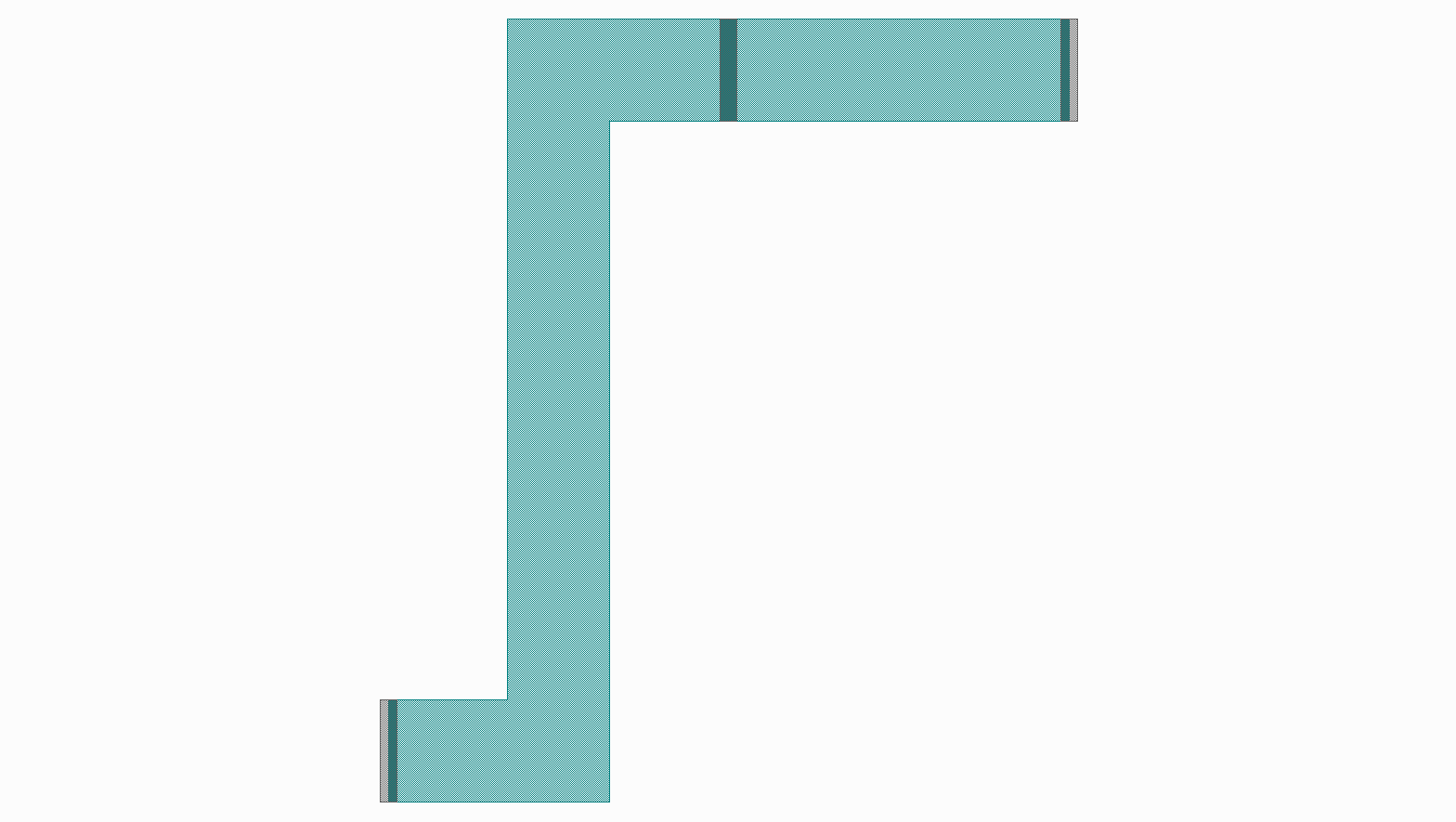
The created Resistor cell can be extended by creating a new cell that inherits from this class.
To extend the elements we have to add the parent class elements to the current instance. This is done
using Python’s super method: elems = super().create_elements(elems). A second route can then
be generated starting from p2 and ending at p3 with a rounded corner bend.
# ...

class ResistorExtended(Resistor):

    p3 = spira.Parameter(fdef_name='create_p3')

    def create_p3(self):
        return spira.Port(name='P3', midpoint=(self.length,0), orientation=90, width=self.width, process=spira.RDD.PROCESS.R1)

    def create_elements(self, elems):
        elems = super().create_elements(elems)
        elems += spira.RouteManhattan(ports=[self.p2, self.p3], corners='round', layer=spira.RDD.PLAYER.R1.METAL)
        return elems

Another method to mimic cell hierarchy is to pass a cell to another cell as a parameter:
class ResistorManhattan(spira.PCell):

    width = spira.NumberParameter(default=spira.RDD.R1.MIN_WIDTH, doc='Width of the shunt resistance.')
    length = spira.NumberParameter(default=spira.RDD.R1.MIN_LENGTH, doc='Length of the shunt resistance.')

    p1 = spira.Parameter(fdef_name='create_p1')
    p2 = spira.Parameter(fdef_name='create_p2')

    def validate_parameters(self):
        if self.width > self.length:
            raise ValueError('`Width` cannot be larger than `length`.')
        return True

    def create_p1(self):
        return spira.Port(name='P1', midpoint=(-self.length/2,0), orientation=180, width=self.width, process=spira.RDD.PROCESS.R1)

    def create_p2(self):
        return spira.Port(name='P2', midpoint=(self.length/2,2), orientation=0, width=self.width, process=spira.RDD.PROCESS.R1)

    def create_elements(self, elems):
        elems += spira.RouteManhattan(ports=[self.p1, self.p2], layer=spira.RDD.PLAYER.R1.METAL)
        return elems

    def create_ports(self, ports):
        ports += [self.p1, self.p2]
        return ports


class ResistorStraight(spira.PCell):

    width = spira.NumberParameter(default=spira.RDD.R1.MIN_WIDTH, doc='Width of the shunt resistance.')
    length = spira.NumberParameter(default=spira.RDD.R1.MIN_LENGTH, doc='Length of the shunt resistance.')

    p1 = spira.Parameter(fdef_name='create_p1')
    p2 = spira.Parameter(fdef_name='create_p2')

    def validate_parameters(self):
        if self.width > self.length:
            raise ValueError('`Width` cannot be larger than `length`.')
        return True

    def create_p1(self):
        return spira.Port(name='P1', midpoint=(-self.length/2,0), orientation=180, width=self.width, process=spira.RDD.PROCESS.R1)

    def create_p2(self):
        return spira.Port(name='P2', midpoint=(self.length/2,0), orientation=0, width=self.width, process=spira.RDD.PROCESS.R1)

    def create_elements(self, elems):
        elems += spira.RouteStraight(p1=self.p1, p2=self.p2, layer=spira.RDD.PLAYER.R1.METAL)
        return elems

    def create_ports(self, ports):
        ports += [self.p1, self.p2]
        return ports


class ResistorConnect(spira.PCell):

    res0 = spira.CellParameter(default=ResistorManhattan)
    res1 = spira.CellParameter(default=ResistorStraight)

    def create_elements(self, elems):
        s1 = spira.SRef(reference=self.res0())
        s2 = spira.SRef(reference=self.res1())
        s2.connect(port=s2.ports['P1'], destination=s1.ports['P2'])
        elems += [s1, s2]
        return elem
We start by creating two resistor classes, ResistorManhattan and ResistorStraight,
then we add them to a single cell instance were we can snap the two structures into place
by connecting their respective instance ports. An instance for each resistor cell is created
using spira.SRef and then P1 of instance ResistorStraight
is connect to P2 of instance ResistorManhattan using the connect() method.
Transformations
Transformations is SPiRA are not directly applied to layout elements. Instead, they are abstraction build as a layer on top of the SPiRA core, and are connected to Elements as parameters. Doing so enable us to transform elements without losing hierarchical data implicit in the layout structure.
Demonstrates
- Understand why transformations are parameterized in SPiRA.
- How to apply transformations to layout elements.
- How to keep the hierarchical structure of a flatened layout.
There are multiple different ways to apply a transformation to a layout element:
- The first method creates a transform object and then applies it to an object.
- The second directly uses a element method to apply the transform.
class TranslatePolygon(spira.Cell):

    ref_point = spira.Parameter(fdef_name='create_ref_point')
    t1 = spira.Parameter(fdef_name='create_t1')
    t2 = spira.Parameter(fdef_name='create_t2')
    t3 = spira.Parameter(fdef_name='create_t3')

    def create_ref_point(self):
        return spira.Rectangle(p1=(-2.5, -2.5), p2=(2.5, 2.5), layer=spira.Layer(number=1))

    def create_t1(self):
        """ Apply transformation by first creating a transform object. """
        T = spira.Translation(Coord(-10, 0))
        ply = spira.Rectangle(p1=(0,0), p2=(10, 50), layer=spira.Layer(number=2))
        ply.transform(T)
        return ply

    def create_t2(self):
        """ Apply transformation by creating a generic transform.
        Instead of using the `.ttransform` method, the transform
        is directly added as a parameter."""
        tf = spira.GenericTransform(translation=Coord(-22, 0))
        ply = spira.Rectangle(p1=(0,0), p2=(10, 50), layer=spira.Layer(number=3), transformation=tf)
        return ply

    def create_t3(self):
        """ Directly transform the element using the corresponding transform method. """
        ply = spira.Rectangle(p1=(0,0), p2=(10, 50), layer=spira.Layer(number=4))
        ply.translate((-34, 0))
        return ply

    def create_elements(self, elems):
        elems += self.ref_point
        elems += self.t1
        elems += self.t2
        elems += self.t3
        return elems
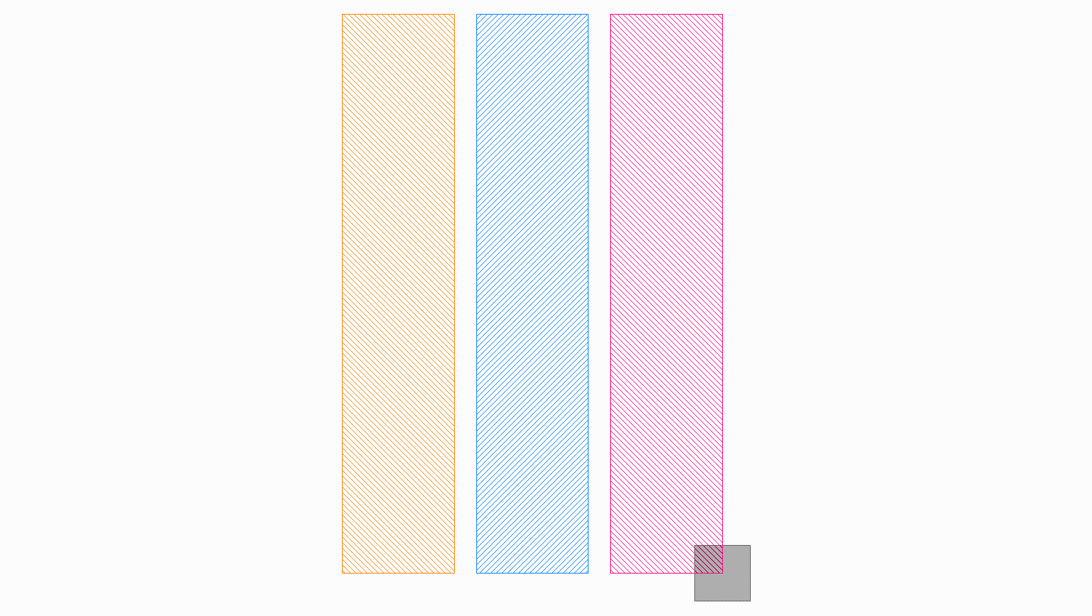
The code snippet above illustrates the different ways to connect a transform to an element.
The first method in create_t1 is typically used when we want to create a set of
predefined transforms and later connect them to multiple elements.
The second method in create_t2 is very similar to that of the first, but instead
manually creates a generic transformation object and connect it to the element as a parameter.
This method is just shown for illustration purposes and rarely used in practice, since a generic
transform is automatically created by the framework when multiple transform objects are added.
The thrid method in create_t3 uses the class method to automatically create the
transform object and emidiately apply the transform to the subject element.
class TransformPolygon(spira.Cell):

    ref_point = spira.Parameter(fdef_name='create_ref_point')
    t1 = spira.Parameter(fdef_name='create_t1')
    t2 = spira.Parameter(fdef_name='create_t2')
    t3 = spira.Parameter(fdef_name='create_t3')

    def create_ref_point(self):
        return spira.Rectangle(p1=(-2.5, -2.5), p2=(2.5, 2.5), layer=spira.Layer(number=1))

    def create_t1(self):
        T = spira.Rotation(30) + spira.Translation(Coord(10, 0))
        ply = spira.Rectangle(p1=(0,0), p2=(10, 50), layer=spira.Layer(number=2))
        ply.transform(transformation=T)
        return ply

    def create_t2(self):
        T = spira.GenericTransform(translation=(20, 0), rotation=60)
        ply = spira.Rectangle(p1=(0,0), p2=(10, 50), layer=spira.Layer(number=3), transformation=T)
        return ply

    def create_t3(self):
        ply = spira.Rectangle(p1=(0,0), p2=(10, 50), layer=spira.Layer(number=4))
        ply.translate((30, 0))
        ply.rotate(90)
        return ply

    def create_elements(self, elems):
        elems += self.ref_point
        elems += self.t1
        elems += self.t2
        elems += self.t3
        return elems
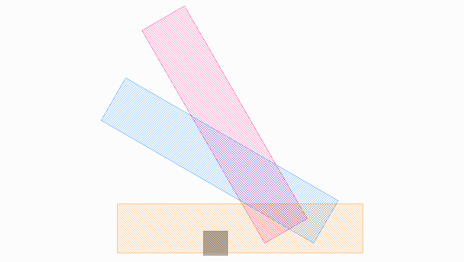
Transformations can be compounded using the plus operator as shown in create_t1.
The result is a generic transformation that can be added to any element. A generic transform
can also be explicitly defined as in create_t2, or multiple transforms can be
adding using the corresponding methods as shown in create_t3.
Stretching
This tutorial builds from the previous tutorial of transformations. Here, we will look at how to stretch a cell reference and specific polygons using ports.
Demonstrates
- How to stretch layout elements.
- How to use expanded transformations to view flattened ports.
- How to stretch a specific polygon while maintaining the layout hierarchy.
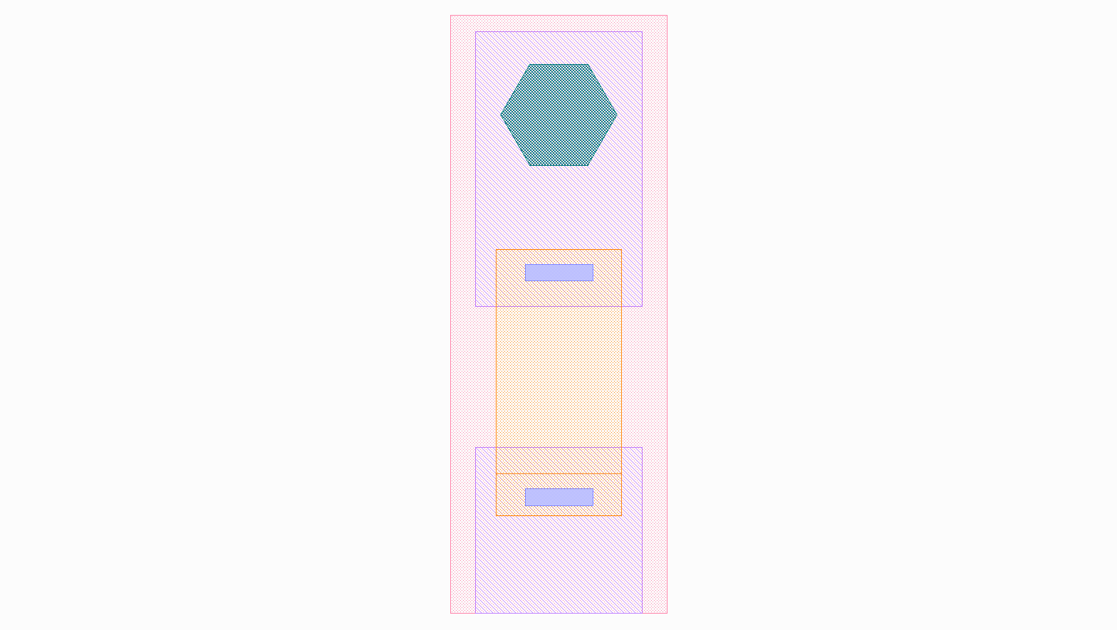
In this example we are stretching an entire cell reference by some factor. We have created a basic Josephson Junction to demonstrate the stretching of different polygons inside the PCell, while maintaining the hierarchical structure.
class Jj(spira.Cell):

    def create_elements(self, elems):
        elems += spira.Convex(radius=7.0, layer=RDD.PLAYER.C2.VIA)
        return elems


class ResVia(spira.Cell):

    def create_elements(self, elems):
        elems += spira.Rectangle(p1=(-7.5, -13.2), p2=(7.5, -8.2), layer=RDD.PLAYER.R1.METAL)
        elems += spira.Rectangle(p1=(-4, -12), p2=(4.1, -10), layer=RDD.PLAYER.C1.VIA)
        return elems


class Top(spira.Cell):

    def get_transforms(self):
        t1 = spira.Translation((0, 0))
        t2 = spira.Translation((0, -8))
        return [t1, t2]

    def create_elements(self, elems):
        t1, t2 = self.get_transforms()
        elems += spira.SRef(alias='Sj1', reference=Jj(), transformation=t1)
        elems += spira.SRef(alias='Sr1', reference=ResVia(), transformation=t2)
        elems += spira.Rectangle(p1=(-10, -23), p2=(10, 10), layer=RDD.PLAYER.M2.METAL)
        return elems


class Bot(spira.Cell):

    def get_transforms(self):
        t1 = spira.Translation((0, 0))
        t2 = spira.Translation((0, -30))
        return [t1, t2]

    def create_elements(self, elems):
        t1, t2 = self.get_transforms()
        elems += spira.SRef(alias='Sr2', reference=ResVia(), transformation=t2)
        elems += spira.Rectangle(p1=(-10, -55), p2=(10, -35), layer=RDD.PLAYER.M2.METAL)
        return elems


class Junction(spira.Cell):
    """ Josephson junction. """

    def get_transforms(self):
        t1 = spira.Translation((0, 0))
        t2 = spira.Translation((0, -5))
        return [t1, t2]

    def create_elements(self, elems):
        t1, t2 = self.get_transforms()
        elems += spira.Rectangle(p1=(-13, -60), p2=(13, 12), layer=RDD.PLAYER.M1.METAL)
        elems += spira.SRef(alias='S1', reference=Top(), transformation=t1)
        elems += spira.SRef(alias='S2', reference=Bot(), transformation=t2)
        return elems
An instance of the Junction cell can be created and added as a reference, which
can be stretched using the stretch_by_factor() method:
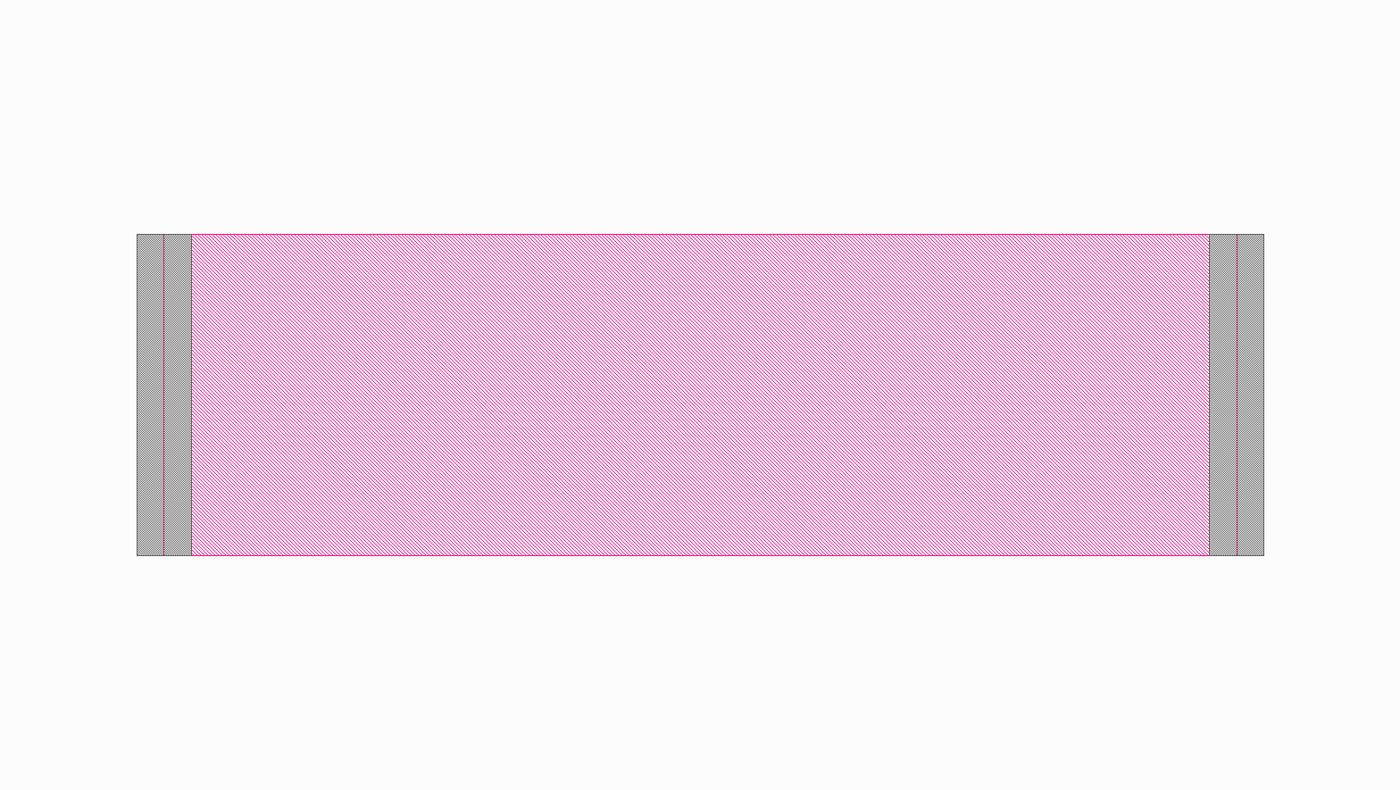
junction = Junction()

C = spira.Cell(name='TestingCell')
S = spira.SRef(alias='Jj', reference=junction)

# Stretch the reference and add it to the cell.
C += S.stretch_by_factor(factor=(2,1))

# Generate an output using the build-in viewer.
C.gdsii_output()
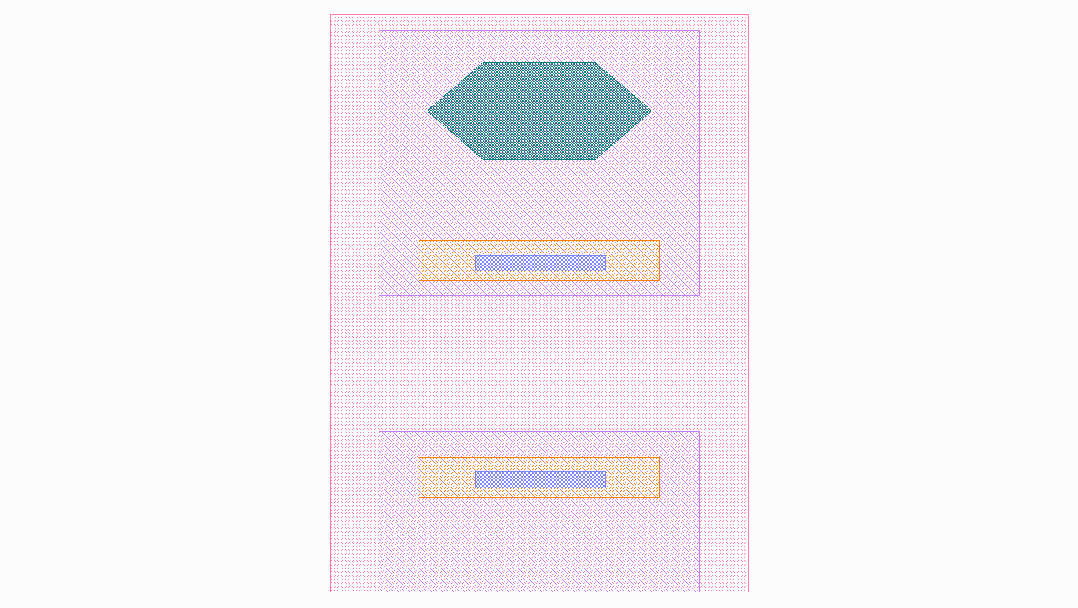
The expanded flattened view of the junction cell is shown below.
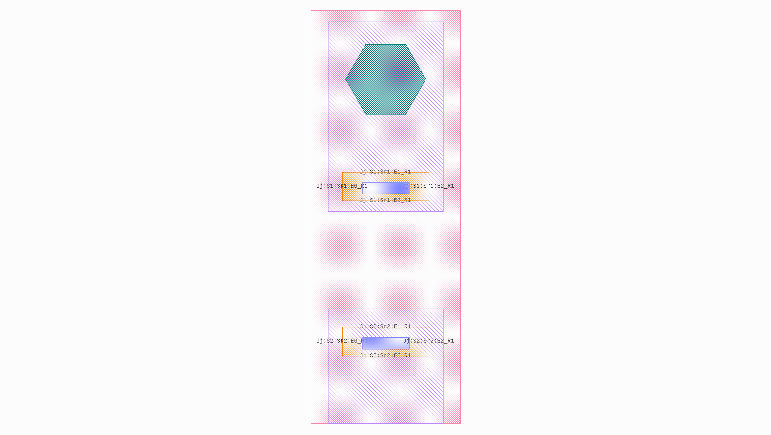
All polygon elements that coalesces this cell is stretched by a factor of two in the horizontal direction (x-axis).
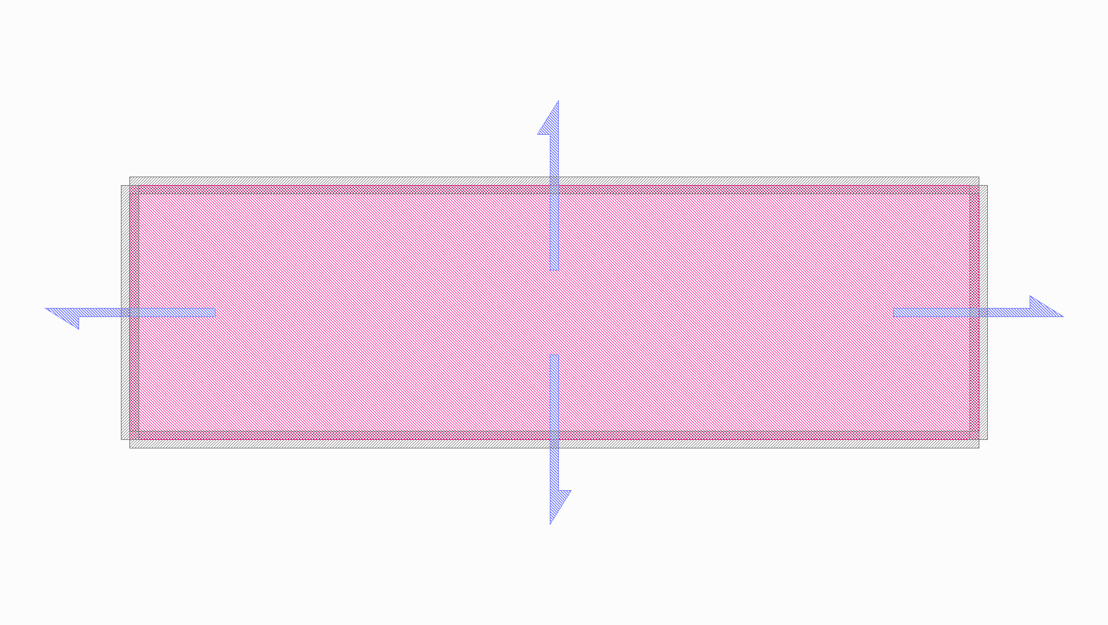
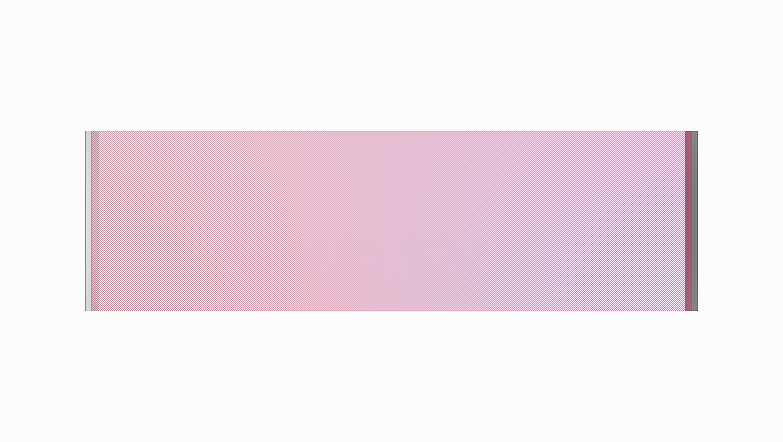
junction = Junction()

C = spira.Cell(name='TestingCell')
S = spira.SRef(alias='Jj', reference=junction)

# Stretch the reference and add it to the cell.
S.stretch_p2p(port_name='S1:Sr1:E3_R1', destination_name='S2:Sr2:E1_R1')

# Generate an output using the build-in viewer.
C.gdsii_output()
The expanded view is used to access flattened ports using their hierarchically derived names. The port names used in the code above are shown in the expanded view of the cell. In this example we want to stretch the two shunt resistor polygons so form a single resistor connection polygon.